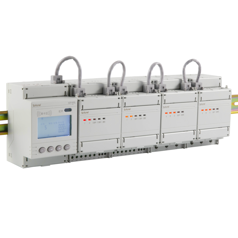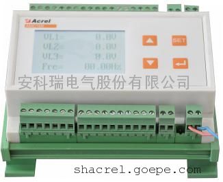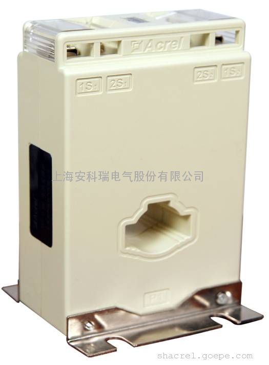
Abstract: This paper introduces the application of ackry APM series AC meter in the AC side of Bulgarian photovoltaic system. It is mainly used to measure the current in the photovoltaic system, and cooperate with the transformers to measure, communicate and control the circuit system.
1.Project Overview
The company is located in Bulgaria. The company is mainly engaged in the design / installation, construction / maintenance of small photovoltaic power generation center projects in Bulgaria and surrounding countries. The customer wants to use AC meters apm801, apm810 and mutual inductors for monitoring, metering and communication of current and voltage at the AC side of photovoltaic system, and control by using the switching value function of APM meter.
2.APM Series Energy Meters
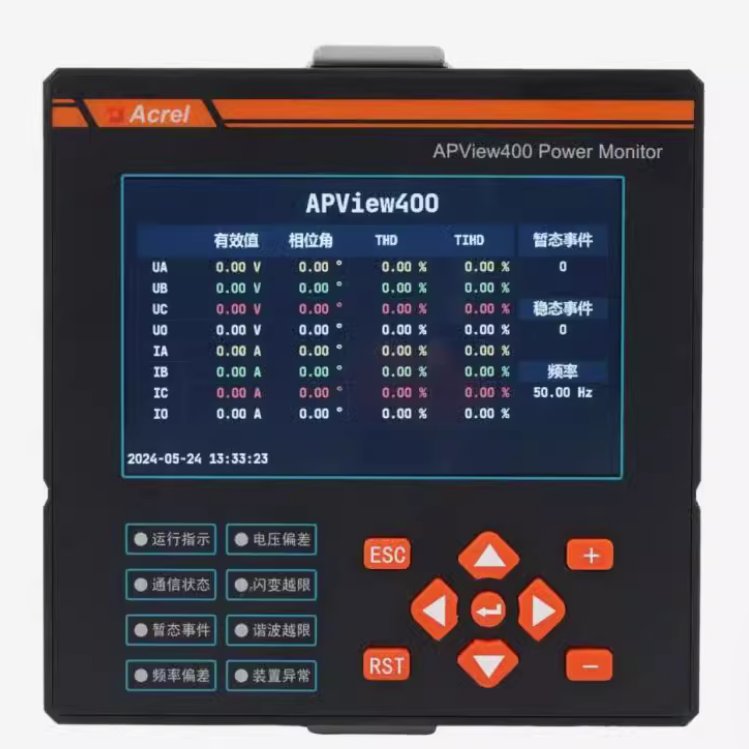
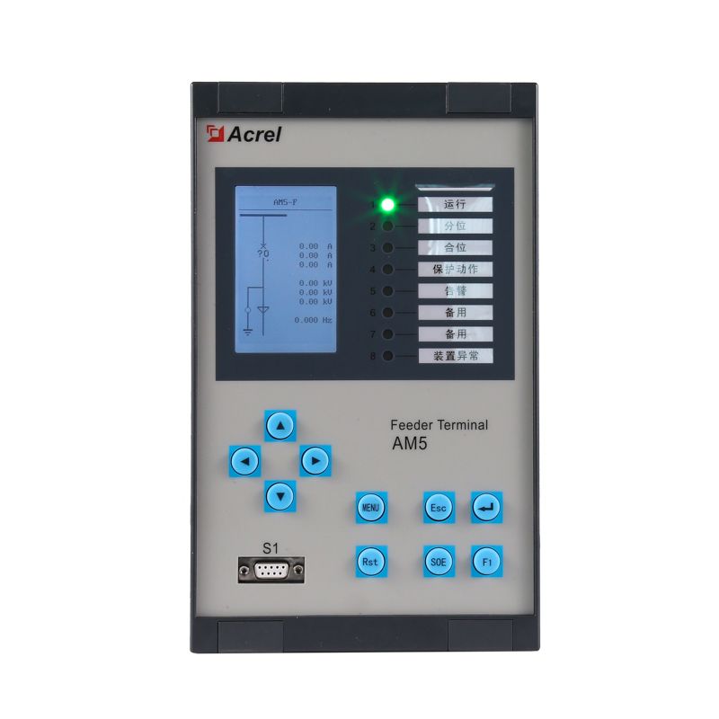
APM series power meters of ACREL are power meters that are designed according to IEC standards and synchronized with international advanced technology.
APM series meters have full power measurement, energy statistics, analysis of power quality and network communications and other functions, are mainly used for comprehensive monitoring of the quality of power supply network.
This series of meters use a modular design, with a rich function of the external DI / DO module, AI / AO module, event recording (SOE) module with T-Flash (TF) card, network communication module, Temperature and humidity measurement module, can achieve full power measurement of electrical circuit and monitoring of switch status, Dual RS485 with Ethernet interface can realize data copying of RS485 master station, eliminating the need for data switching exchange. PROFIBUS-DP interface can realize high-speed data transmission and networking function.
3.Type and Function Description
4.Technical parameters
5.Requirements from Customer
terms of reference from grid supplier:
(1)monitoring voltages: L1-N, L2-N, L3-N. Unominal = 230V;
(2)switching relay output at overvoltage: 2 steps:
Step 1: 110% of Unominal or 253V - delay 60 seconds (s) ;
Step 2: 115% of Unominal or 264V - delay 0.1s;
(3)switching relay output at undervoltage:
1-step; 80% of Unominal or 184V - delay 0.2s; Range of settings: U: 10-100% of Unominal, step not listed, maybe 1V ot 1%; Delay: 0.05 s to 3s, step - not listed, maybe 1s;
(4)switching relay output at overfrequency
1-step; 50.5Hz - delay 0.1s; Range of settings: F: 50-52.5Hz, step 0.1Hz; Delay: 0.1-0.5s, step - maybe 0.1s;
(5)switching relay output at overfrequency
1- step; 47.5Hz - delay 0.1s; Range of settings: F: 47.5-50Hz, step 0.1Hz; Delay: 0.1-0.5s, step - maybe 0.1s;
(6)Delay for recovering. When DO is on by some of previous reasons, there should be time delay after grid parameter(s) are back in nominal range(s). Time range 1-60s, step 1s
(7)Additional settings. (If they are possible).
7.1 When Unominal is lower than 60-70%, under and overfrequency monitoring can be disabled
7.2 When overfrequency/underfrequency is happened - the DO should not be recovered automatically, it should wait for some kind of manual/remote restore.
The above 7 items are the special needs of customers for the purchased products. Except that some requirements in point 7 cannot meet the needs of customers, other needs can be met. Basically solved the needs of customers.
6.Installation Picture
Bibliography
1.Solutions For Enterprise Micro-grid System 2021.04

 安科瑞电气股份有限公司13611965514内容声明:谷瀑为第三方平台及互联网信息服务提供者,谷瀑(含网站、客户端等)所展示的商品/服务的标题、价格、详情等信息内容系由店铺经营者发布,其真实性、准确性和合法性均由店铺经营者负责。谷瀑提醒您购买商品/服务前注意谨慎核实,如您对商品/服务的标题、价格、详情等任何信息有任何疑问的,请在购买前通过谷瀑与店铺经营者沟通确认;谷瀑上存在海量店铺,如您发现店铺内有任何违法/侵权信息,请在谷瀑首页底栏投诉通道进行投诉。安科瑞电气股份有限公司 电话:021-69153629 手机:13611965514 地址: 上海市嘉定区育绿路253号
 扫一扫,手机浏览
